Over time, the rubber tires on the feeder wheels of your PhyzBatch-9000 may wear and need replacing. This should only occur after at least one million cards have been sorted, barring some sort of tire defect. If the wheels need replacing, there should be noticeable wear or tearing. PhyzBatch-9000 machines currently ship with one additional set of tires.
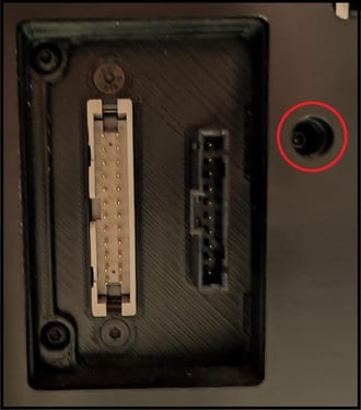
The steps involved in replacing your wheels depend on the specific model of PhyzBatch you have. Click on the image below that corresponds to your model for the correct steps.


No Screw
Tools:
- 1.5mm Allen Key
- 2mm Allen Key
- screwdriver or 5mm Allen key
- Remove the extended hopper, if installed.
- Remove the scanner from the chassis.
- Remove the hopper wedge from the top of the machine (4x2mm).

- Remove the following screws (20x2mm).


- Remove the screw (1x2mm) holding the gate tray, and pull the tray out.

- Remove the tail assembly from the front of the machine. Loosen and remove the front tails, the thumbscrew, and the two screws (2x2mm) on the left side. Note that removing the thumbscrew will cause a mount inside the side door of the scanner to fall. It should be retrieved for later reinstallation.


- Loosen the screws in the feed wheels.
- If your feed wheels have 1 screw each, use a 1.5mm Allen key.
- If your feed wheels have 2 screws each, use a 2mm Allen key.
The grub screws for the wheels and pulley in the next steps are very small. It is best to simply loosen, rather than entirely removing them. Take care not to lose the screws!
- Remove the scanner body (the aluminum frame) from the housing (black, anodized aluminum). The housing walls can be flexed to get them around the screw mounts. The front left corner (next to the hopper) is stiffer due to its location at a corner and may require leverage from a screwdriver or Allen key.

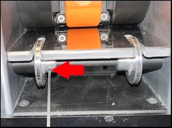
The frame can be angled to the side or completely removed from the housing. Both present advantages: Easier reassembly, or better access for the next step. The purpose is to get access to both sides of the feed wheel drive shaft, as shown below.
- Loosen the screws on the feed wheel pulley (2x1.5mm). Once loosened, you should be able to hold the pulley still and spin the shaft freely. If there is resistance, continue to loosen the screws.

- Push the shaft into the pulley, pulling it out from the far side, far enough that you can slide the feed wheels off of it. Note that in the example, the wall bearing has been pushed out with the shaft. When reinstalling the shaft, this bearing will need to be pressed into the scanner housing again.

Inserting a screwdriver or your largest Allen key (5mm) through the pulley, bearing, and (on some models) plastic spacer in place of the shaft you're removing can keep them positioned correctly for easier shaft reinstallation.
If at any point you drop a tool or part into the interior of the scanner, you can partially move the controller board mounting plate for easier access. Remove the following screws (2x2mm), and angle the board out of the way. It cannot be fully removed due to the wiring.

- Exchange the rubber on the wheels. In most cases, the rubber may simply be pulled off.
Some feed wheels may have the rubber glued in place. To remove it, fully remove the wheel screws, then soak the wheel and rubber in isopropyl alcohol for 2-24 hours. After soaking, remove the tire and clean out any residual glue or rubber with a toothpick. Fully dry the wheel before installing the new tire. Replacement glue is not required, and can, in some cases, lead to earlier tire degradation.
The rubber tires have a slightly narrowed inner side and a wider outer edge. Make sure that the wider side is facing outwards when installing the tire.
- Reverse the above steps to reassemble your scanner.
- When lining up the wheels on the shaft, note that the shaft has 2 notches where the wheel should sit. It is recommended that the shaft be reinstalled, the pulley screws tightened, before lining up and tightening the screws on the wheels. Above all, once tightened, the wheels must not touch the hopper landing plate, and cannot move side-to-side.

- Once the wheel screws are tightened, ensure that the wheels cannot turn independently of the shaft or each other, by holding one of them at a time and turning the shaft by hand (best to grip the pulley).
After reinstalling the wheels, you temporarily plug the machine back in and can run the "Clean Feed Wheels" command in the Maintenance menu to ensure they are turning properly. Unplug the machine again before reinstalling the housing and other parts.
Screw
Tools:
- 1.5mm Allen Key
- 2mm Allen Key
- T10 Torx bit (depending on model)
- screwdriver or 5mm Allen key
- The scanner and extended hopper may be left attached for this procedure.
- Remove the side panel from your PhyzBatch (10x2mm).

- Remove the tails from the front of the machine, then the tail mount itself. You may have one of several iterations of tail mounts. Instructions for each are:

- Remove the screws (4x2mm), then pull the mounting plate off.


- Remove the screws (5), then pull the mounting plate off.
Depending on your model, these screws may be either a hex head (2mm Allen key) or a Torx head (T10).
- Loosen the screws on the feed wheel pulley (2x1.5mm). Once loosened, you should be able to hold the pulley still and spin the shaft freely. If there is resistance, continue to loosen the screws.
- Push the shaft into the pulley, pulling it out from the far side, far enough that you can slide the feed wheels off of it. Note that in the example, the wall bearing has been pushed out with the shaft. When reinstalling the shaft, this bearing will need to be pressed into the scanner housing again.

Inserting a screwdriver or your largest Allen key (5mm) through the pulley, bearing, and plastic spacer in place of the shaft you're removing can keep them positioned correctly for easier shaft reinstallation.
If at any point you drop a tool or part into the interior of the scanner, you can partially move the controller board mounting plate for easier access. Remove the following screws (3x2mm), and angle the board out of the way. It cannot be fully removed due to the wiring.

- Exchange the rubber on the wheels. In most cases, the rubber may simply be pulled off.
The rubber tires have a slightly narrowed inner side and a wider outer edge. Make sure that the wider side is facing outwards when installing the tire.
- Reverse the above steps to reassemble your scanner.
- Note that there is a small black spacer between the bearing and the pulley on the feed wheel shaft.

- When lining up the wheels on the shaft, note that the shaft has 2 notches where the wheel should sit. It is recommended that the shaft be reinstalled, the pulley screws tightened, before lining up and tightening the screws on the wheels. Above all, once tightened, the wheels must not touch the hopper landing plate, and cannot move side-to-side.

- The black plastic spacers can be used to indicate the correct position of the wheel.
After reinstalling the wheels, you temporarily plug the machine back in and can run the "Clean Feed Wheels" command in the Maintenance menu to ensure they are turning properly. Unplug the machine again before reinstalling the housing and other parts.